How many sensors to install?
diciembre 04 2020
For an application that has been around for more than 30 years, this basic question is remarkably still one of the first ones we are asked when talking to asset owners and consulting engineering companies.
In a nutshell, OEM Transformer manufacturers would like to install as few as possible for both cost and warranty reasons, while Utility and Asset Owners would like as many as possible to ensure there is a sensor placed at the hottest spot in the windings and the benefits from monitoring is assured.
In the beginning: IEC 60076-2 Annex E
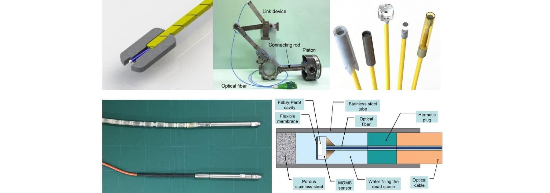
In 2011 the IEC released the updated standard, Temperature rise for liquid-immersed transformers, where a new Annex E was added, Application of optical fibre sensors for winding hot-spot measurements.
Tables E.1 and E.2 in Annex E defined the recommended number of sensors based on the rated power in MVA, number of phases, and type of cooling system of the transformer.
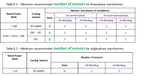
This IEC guide proved to be a decent starting point for most asset owners and for the next 5 years after its release our experience at FISO reflected the guidance within, as we saw the majority of projects specifying 6-8 channels per transformer.
Due to the release of that IEC standard the practice of installing temperature probes for hot-spot monitoring experienced a boom in adoption. The number of new users increased dramatically and the analyzing of data from these installations resulted in the sharing of insightful case studies for the next wave of users to consider.
Recent Industry Guidance
In 2015 IEEE released the standard 1538a-2015, Determination of Maximum Winding-Temperature Rise in Liquid Immersed Transformers. The guidance from this standard was an increase in the number of sensors with 4, 6, or 8 sensors per winding recommended, depending on the total leakage flux per phase at rated current.
In 2016 CIGRE Working Group A2.38 followed up with their new guide, publication #659 Transformer Thermal Modeling which echoed the guidance from IEEE at 4, 6, or 8 sensors per winding.
In 2018, to bring the story full circle, some seven years after their breakthrough Informative guide, IEC released a new publication, Loading Guide for Mineral Oil Immersed Power Transformers where they came to the same conclusion as the IEEE and CIGRE documents noted earlier. More sensing locations were needed.
With various combinations possible, such as: (i) 4, 6, or 8 sensors per winding, (ii) single-phase or three-phase, and (iii) transformer rated power, the guidance from IEC/IEEE/CIGRE results in from 4 to 24 channels being possible for winding direct hot spot monitoring alone on each transformer.
As IEC 60076-7 states quite aptly, “the use of fiber optic temperature sensors has become standard practice, however, the number of installed sensors per transformer highly varies”.
So where does that leave us in answering the question?
FISO’s Guidance
While the industry standards are an excellent starting point, the owner needs to consider additional criteria such as (i) the criticality of the asset, (ii) the need to monitor temperature at other locations such as core/ top oil /ambient, (iii) the expected load and loading profile on the transformer, (iv) the associated costs, and (v) their experience with a particular transformer manufacturer.
The table below reflects our experiences and while none of the transformer classifications reflects a specific Industry Standard, the summary is a good reflection of the decisions being made by asset owners today. (We reserve the right to update in the future!)
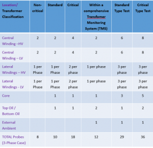
While the transformer classification is key in determining the number of sensors to install, some further explanation and insight into how the asset owners are making this determination follows:
Criticality of Asset
A large power plant GSU or key commercial site such as an oil refinery, airport, or remote mine might warrant more investment in monitoring, due to the financial impact of any power interruption. In contrast, a HV substation with several identical transformers might get by with fewer sensors due to design similarity and redundancy at the location.
Adding non-winding locations
Once a system in installed with “X” channels monitoring winding hot-spots, the incremental cost of adding a few more channels to capture temperatures at other locations within the transformer is worth considering. These locations include:
- Inside core, core surface, yoke clamps & extensions
- Top oil(s) and bottom oil
- Ambient temperature
Expected load and loading profile
A transformer which is expected to be run near or at rated load would definitely justify the small incremental cost of more sensors in order to maximize the lifetime of the transformer. Similarly, a transformer which will experience dynamic loading would also see increased adoption and investment, such as those at solar park and wind farm projects.
Associated Costs
Adding the sensors and monitoring system does come at a price and although systems are only a tiny fraction of the transformer price, budget is always a consideration. In order to control costs, asset owners have the option to purchase systems directly from the monitoring system manufacturers and provide the system components to their designated transformer OEM factory for installation and commissioning.
Based on Experience with Transformer Manufacturer
A bad experience or reputation can lead to direct monitoring being a non-negotiable requirement of purchase, with many sensors added to ensure a thorough quality check.
Summary
At the end of the day the number of sensors installed is an economic choice made by the asset owner based on the benefits derived from the investment. We hope that the guidance and industry insight provided in this article prove helpful when making that choice.
FISO would like to thank the International Electrotechnical Commission (IEC) for permission to reproduce Information from its International Standards. All such extracts are copyright of IEC, Geneva, Switzerland. All rights reserved. Further information on the IEC is available from www.iec. ch. IEC has no responsibility for the placement and context in which the extracts and contents are reproduced by the author, nor is IEC in any way responsible for the other content or accuracy therein.
FISO also thanks the IEEE for permission to reproduce Information from its International Standards. The IEEE standards or products referred to in this clause are trademarks of The Institute of Electrical and Electronics Engineers, Inc. All rights reserved. IEEE publications are available from The Institute of Electrical and Electronics Engineers (http://standards.ieee.org/). IEEE has no responsibility for the placement and context in which the extracts and contents are reproduced by the author, nor is IEEE in any way responsible for the other content or accuracy therein.