Comparison of 200um vs 62.5um Fibers
Kasım 06 2020
Two different fiber optic (FO) cable technologies are available for the energy market, one using 200 μm diameter fiber and one using 62.5 μm diameter fiber. Here we discuss the differences between the two fibers.
History
200 μm fiber became established first (in the 1980s) because industry pioneer Luxtron used fluorescence decay, a technology that needed large core fibers due to its inefficient collection of light.
That technology uses a high-energy (low-wavelength) “flashing” light source to activate a chip made of fluorescent material at the tip of the fiber. Because the amount of light emitted by the fluorophores in the chip is miniscule, as large a “light pipe” as possible is used to gather the emitted light. The need for large core fibers is the Achilles heel of fluorescence decay technology.
Back in the 1980s Nortech (the second pioneer) used 200 μm core fiber in developing a manufacturing process with GaAs technology, following in the footsteps of Luxtron.
Over the 1990s and 2000s these companies explicitly specified 200 μm optical fibers in their work with end users and utilities (FISO purchased Nortech in 2001). Those early days were marked by extensive sensor breakage. Almost every OEM that installed sensors at that time adopted a healthy “spare” strategy in case of breakage. Newcomers in the 2000s were forced to use 200 μm because that was “the spec.”
In 2011 with the release of IEC 60076-2 Annex E recommending the installation of FO sensors for winding direct hotspot monitoring, FISO took the opportunity to modernize its sensors and make them more reliable. Hence, the move to an IEC/TIA/IEEE standard fiber called “OM1” (which can be either 62.5 μm or 50 μm core).
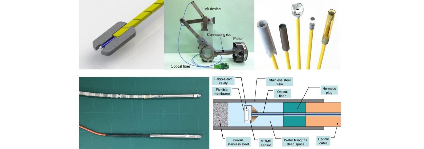
Why can 62.5 μm core fibers be used with GaAs?
GaAs works by direct transmission through the crystal, with >99% of light reflected at the sensor tip traveling through the GaAs crystal going back to the monitor. This results in highly efficient light transmission in the optical system.
Summary
Today, 200 μm is still in use due to marketing alone. The two decades of work to put 200 μm into specifications has been slowly undone over the past decade, with small core MM fibers (62.5 μm/50 μm) now included in many new specifications. OM1 has better optical and mechanical properties and is more reliable than the first generation 200 μm optical fibers introduced in the 1980s.
Facts about the differences
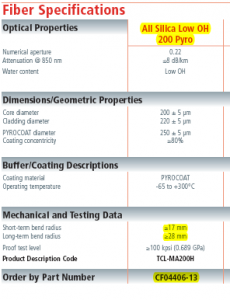
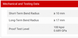
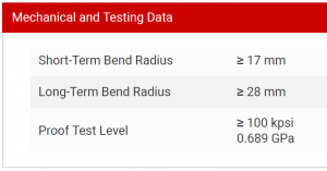
As already mentioned in the chapter on history, 62.5 μm fiber is better than 200μm fiber. Manufacturers of FO cables can provide both fiber diameters, and their datasheets show the features of each FO cable. Image 1 below shows the features of 62.5 μm fiber and Image 2 shows those of 200 μm fiber.
Image 1 :
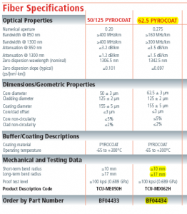
Image 2:
For easier comparison, the features are summarized in Table 1:
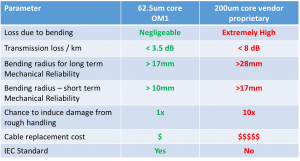
Below we discuss a few of the differences.
Loss due to bending
Loss due to bending is much higher in 200 μm fiber than in 62.5 μm fiber. This can be a problem when routing the fiber in the transformer to the tank wall. Overall bending can lower signal quality significantly. With 200 μm fiber, the manufacturer must always find the shortest route to the transformer tank wall in order to reduce bending as much as possible. Note that clamping a FO cable is also considered bending. With 62.5 μm fiber, the manufacturer has much more flexibility in routing the fiber in the transformer.
Long- and short-term bending radius
The minimum bending radius is a measure of how much a FO cable can be bent before it breaks. Obviously, it indicates the durability of the cable itself.
Long-term and short-term bending radius is lower in 62.5 μm fiber. This means the fiber is much more robust.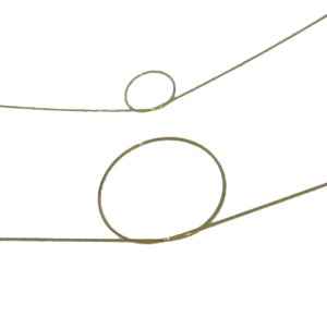
Short-term bending radius is important during installation. When fiber is routed through the transformer, many bends appear. Each one can break the fiber. If a fiber breaks during the transformer manufacturing process, you can imagine the high costs and unhappy customers.
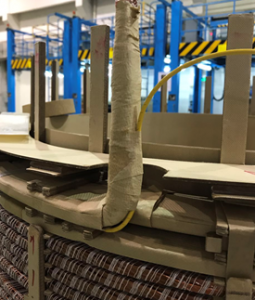 Long-term bending radius becomes an issue after the factory acceptance test (FAT). Sensors might work just after installation but fail during transportation from the manufacturer’s factory to the customer’s substation. Over the transformer’s life cycle, many things can put physical stress on the installed FO temperature sensors, such as moving the transformer, a short circuit, or any other physical impact. If the FO cable is not very durable, the installed sensors might fail.
It is easier to induce micro-cracks in 200 μm core fiber than in 62.5 μm core, which has 10x the surface area and exhibits higher tensile strength on the outer edge when bent. With 200 μm it is easier to cause a crack, and it is easier for any existing cracks to expand. Cracks continue to grow over time and with temperature cycling. Crack growth after initial fracture is ultimately the reason fibers break (if not due to a sudden impact).
Cable replacement cost
As already mentioned, 62.5 μm fiber is standard in the telecom industry. That means it is readily available, is less dependent on the manufacturer, and less expensive. 200 μm fiber is a custom solution that is not readily available.
Let us assume a fiber breaks during transformer installation because it is hit with a hammer. That fiber can be repaired. If 200 μm fiber is used, the repair must be performed by the FO manufacturer or a certified specialist. If 62.5 μm fiber is used, the local telecom dealer/specialist can be contacted to help, since this is the standard size. In some cases, special used shielding information must be provided so the telecom specialist can solve the problem on the spot. The same is true if connectors are required, as 62.5 μm connectors are known and available, while 200 μm connectors are not.
Pull test
Image 3 shows the testing data of 62.5 μm fiber and Image 4 shows the testing data of 200 μm fiber.
The main mechanical spec for fiber is the proof test level. This is the holding force (pull strength) of the fiber tested and guaranteed by the fiber manufacturer.
Image 3: 62.5 μm fiber
 I
I
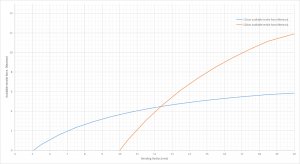
Looking at pull strength alone, you see that 100 kpsi gives 8.5 newtons for 62.5 μm fiber vs. 26 newtons for 200 μm fiber. Note this is for a straight pull only. The weakest link is in the CURVE. To find out available tensile force, you must take the fiber’s guaranteed 100 kpsi and subtract the bending stress. Graph 1 below shows that both fibers have an equal available force at a bendingradius of 12.4 mm. But be aware that the minimum bending radius in your transformer may be less than that. At 10 mm there is no remaining strength in 200 μm fiber but 2.8 newtons still available in 62.5 μm fiber. 62.5 μm fiber can be bent as much as 5 mm, twice as much as 200 μm fiber, which is why FISO introduced the TPT-62 (62.5 μm fiber) ten years ago and why it now represents 99.9% of our hotspot sensor sales.
Image 4: 200 μm fiber
Graph 1
Conclusion
Standard 62.5 μm technology gives transformer manufacturers and customers flexibility, predictability, and cost saving. It’s the most durable state-of-the-art technology, and customers will be able to readily find spares and monitors for the whole lifetime of the transformer.