Temperature in Switchgears
Nisan 01 2021
Introduction
Middle voltage (MV) switchgears are one of the main components of electrical power grids. MV switchgears are used to connect or disconnect MV assets such as motors and transformers. Switchgears have two main parts, the secondary compartment and the primary compartment. The secondary compartment contains all low voltage components, which are used for controlling, whereas the primary compartment contains all middle voltage components. Clearly, the primary compartment is the more critical part of the switchgear. Figure 1 shows a switchgear with its main components.
The role of temperature in the switchgear
MV switchgears can have rated currents of up to 5000 A. Such high currents can create high temperatures, which can damage the switchgear. High temperatures can cause melting, corrosion or even burning inside the switchgear, which every operator wants to avoid.
Normally all switchgears are type tested, which means that temperatures will not exceed critical values as long as the switchgear does not exceed its rated parameters such as maximum rated current. Unfortunately, there are many other circumstances that can cause an increase in temperature:
- Improperly connected bus bar joints
- A partial discharge that increases over time
- The use of different components, e.g., a type-tested switchgear corpus from manufacturer X and a type-tested circuit breaker from manufacturer Y
- External effects such as dust or high ambient temperature due to a broken AC system or bad ventilation
- Overloading of the switchgear
- Age of the switchgear and its components
This shows that high temperatures are possible, not unusual and dangerous.
Critical areas inside the switchgear
As in the transformer, the weakest point inside the switchgear is its hottest spot. Knowing the hots spots makes it easier to control and monitor their temperature. Hot spots are found mainly where one part connects to another part, shown as red dots in Figure 1. The most critical hots spots are in the bus bar and the cable joints. However, this can differ from one manufacturer to another.
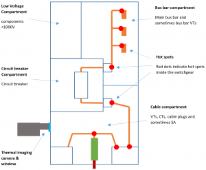
Figure 1: Switchgear with its compartments and components
Temperature monitoring
Temperature is a key factor in extending equipment life. That is why operators use devices to monitor the temperature of their switchgears. Some devices are installed inside the switchgear and provide continuous monitoring, whereas most are used at certain intervals only. Below is a description of FISO’s solution for monitoring MV switchgear temperatures.
Advantages of using FISO’s FO solution
FISO uses fiber optic (FO) wires in its system to measure the temperature inside the switchgear. FO technology offers numerous advantages.
Using FO technology, manufacturers can install sensors wherever they expect hot spots in the switchgear. No additional type tests are required since no metal parts are used and no current runs through the sensor, only light.
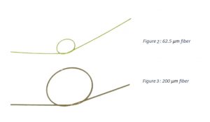
FISO’s 62.5 μm fiber, which is the standard in the telecom industry, reduces failure rates and minimizes costs compared to 200 μm fiber. It is also much more flexible. A more detailed comparison of both FO technologies can be found here.
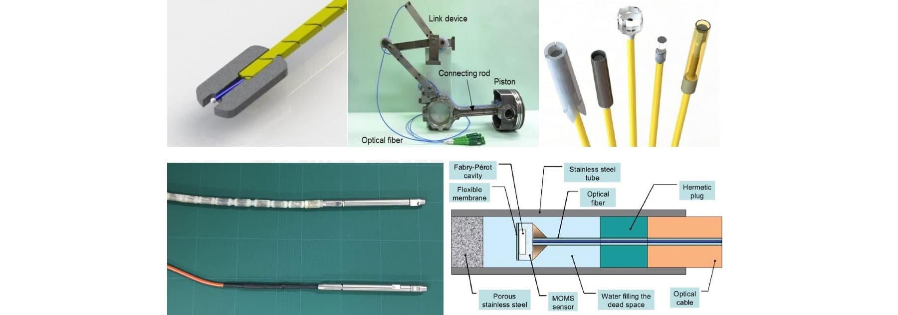
Tiny, flexible 62.5 μm gallium arsenide fiber optic sensors can be installed in narrow spaces such as cable joints.
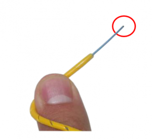 Figure 4: GA sensor
Full immunity to electromagnetic interference (EMI)
Sensor response time: 500 ms (typical)
No recalibration needed
Temperature range -40°C to +225°C (lower temperatures are also possible when needed)
Resolution 0.1°C
Accuracy ±1°C for the sensor and ±2°C for the whole system
Solution for MV air insulated switchgears (AIS)
The whole system consists of only two main parts when installed in an AIS. It is composed of a sensor and a reading unit.
The sensor itself must be attached to the hot spot in the switchgear. Several possibilities for fastening the sensor exist. If you need help attaching the sensor in a specific switchgear, please contact FISO. Below is a photo of a sensor on the bus bar of an AIS.
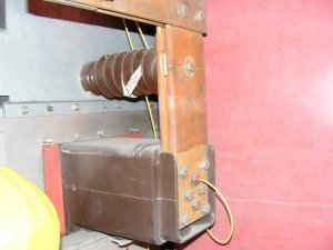
Figure 5: Sensor in an AIS
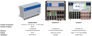
Once the sensor is attached to its hot spot, it must be connected to the reading unit. FISO offers three different monitors/reading units.
Solution for MV gas insulated switchgears (GIS)
When installing the sensor inside a GIS, the challenge is the gas compartment. Therefore, a flange must be installed on the tank wall of the GIS. The flange contains the FISO EasyThrough (20 bar pressure), which is a kind of a bushing.
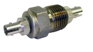
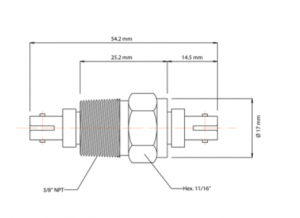
Figure 6: EasyThrough
The sensor is connected to one side of the EasyThrough and an FO extension is connected to the other side of the EasyThrough and the reading unit.
Conclusion
Using FISO’s hot spot temperature monitoring in AIS and GIS is a huge plus for both the end user and the manufacturer. The end user gets a mature, robust and precise product. For the manufacturer, it means easy, flexible installation inside the switchgear. FO temperature monitoring is more precise and durable (>30 years) than other temperature monitoring technologies.
- Robust design
- Proven immunity to EMI
- Resistant to chemicals & vibrations
- No drift, no recalibration required
- Easy to install
- Highly precise