5 things to consider when specifying direct temperature monitoring for your transformer
October 20 2020
 Direct temperature monitoring (DTM) is a technology that has grown substantially over the last decade. The reasons for this are clear (find out more about the benefits of DTM by clicking here!) and are well known by end users. When it comes to specifying DTM, most end users do not know where and how to start. Most end users specify only the need for DTM and maybe the number of sensors. If a system is not specified properly, the end user may pay more or end up with a poor quality system based on old technology. The problem with DTM is that the sensors cannot be changed once installed—hence it is needed to accurately specify DTM in consideration of the entire lifetime of your transformer.
Below is a checklist for specifying your DTM.
1. Number of sensors
The number of sensors has a direct impact on price for the whole DTM system. To choose the right number:
- See IEC 60076-2 ANNEX E. It describes the minimum required number of sensors depending on transformer load, type, and cooling method.
- If the transformer provides power for critical customers such as hospitals, server farms, and so on, consider specifying more sensors.
- Specify more sensors for high transformer ratings (e.g., > 200 MVA and 200 kV).
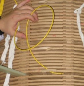
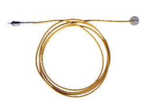
2. Type of FO cable
Currently two types of FO cable are used for DTM, 200 μm and 62.5 μm, with 62.5 μm being the latest type. It was introduced in 2011 to meet IEC 60076-2 ANNEX E requirements, which were officially announced that same year. Make sure you specify the latest technology. 62.5 μm cable has the following benefits for end users:
- It meets the latest IEC 60076-2 ANNEX E requirements.
- It is a future-proof technology. You can be sure parts and monitors will still be available in 30, 40, or 50 years.
- 62.5 μm is also a standard in the telecom industry, which means you can get adapters, connectors, external FO cable and repairing from your local telecom dealer. 200 μm cable is a custom solution that requires special treatment and supply chains.
- Technical benefits of 62.5 μm fiber versus 200 μm fiber:
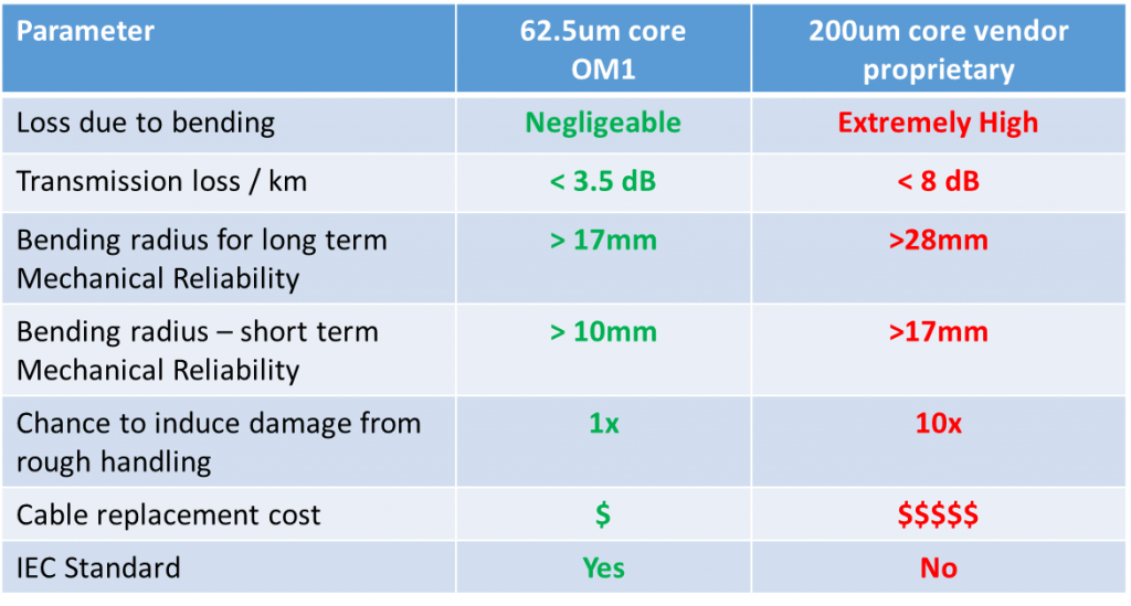
- A more in-depth comparison of both fibers can be found here: https://fiso.com/wp-content/uploads/2020/10/Comparison-of-200um-vs-62.5um-Fibers.docx
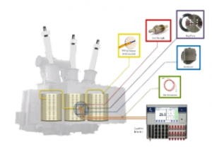
3. FO bushings and plate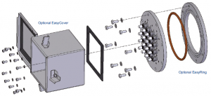
Now you need to get out with the FO cables from the transformer inside to the transformer outside. Therefore, the system on the right is used. The “bushings” are screwed into a plate. This is important to specify properly, because the bushings are a potential source of oil leakage that you will want to avoid.
- FO bushings should withstand high pressures such as 20 bar.
- FO bushings should be delivered to the transformer manufacturer already screwed into the stainless steel plate. This reduces oil leakage to a minimum since the DTM system manufacturer has a special installation process that avoids almost all leakage.
- The number of holes in the FO bushing plate should be equal to the installed number of sensors. Any plugs that seal blind holes on the FO bushing plate are a potential source of oil leakage. That should be avoided.
4. Monitor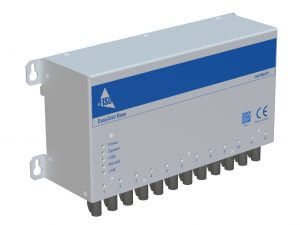
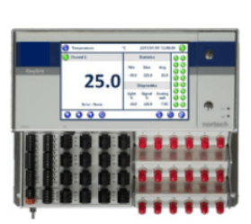
The temperature-monitoring device is a main part of the whole DTM system. Specifying it is not too complicated since there are only a few things to consider:
- Communication protocol. Know which communication protocol your SCADA system needs. The possibilities include:
- Modbus (ASCII/RTU), Modbus TCP-IP, IEC 61850, IEC 60870-5-104, DNP3.0.
- Communication via copper or fiber.<
- Whether PRP over FO is required. If so, it should be integrated into the monitor itself without any additional hardware to reduce costs and the potential of faults.
- Number of auxiliary relays. Do you want to control the transformer fans or any other devices directly with relays on the monitor? If so, specify the number of relays.
Do you want a monitor with a screen? A screen lets you see the temperature of each sensor on site, at the transformer. If you only need to see temperatures in your SCADA system, specify no screen to save money.
If you need a screen, make sure it is possible to see all temperature values at once.
5. Cite the IEC standard and parts of it
IEC 60076-2 ANNEX E clearly indicates what to consider when specifying FO temperature monitoring or so-called DTM. You should cite parts of the IEC 60076-2 ANNEX E standard in your specifications and also mention the standard itself. You may want to cite the following parts:
- “The sensors should be placed in direct contact with the insulation of the winding conductors”[1]
- “The sensor should be placed at the center of the spacer. For avoiding reading errors, the movement of oil around the sensor head should be impeded reducing to the minimum the dimensions of the channel made on the spacer or/and blocking the entry.”[2]
- “Because of the intrinsic fragility of sensors and optical fiber cables, attention shall be paid for avoiding dangerous mechanical stresses and vibrations during the manufacturing process and in operation”[3]
[1] Source: IEC 60076-2 ANNEX E
[2] Source: IEC 60076-2 ANNEX E
[3] Source: IEC 60076-2 ANNEX E